INTRODUCTION
Chiropractic adjustment of the cervical spine is a procedure often considered as a treatment for neck pain. Data from 2012 and 2014 estimate that 8% to 14% of United States adults had been to a chiropractor as a patient in the past year,1,2 and chiropractic utilization has been increasing [7.7 million in the year 2000,3 19.1 million in 2012.1]. It is unclear how many cervical adjustments are performed, but estimates suggest that 22.5% to 30.6% of chiropractic visits are for neck pain.1,4 Terminology may also be unclear; cervical “adjustment” is also known as “manipulation” or “spinal manipulative therapy”, terms which this current report will regard as synonyms. Whatever label may be preferred, our concern here is with high-velocity, low-amplitude (HVLA) thrusts.
The investigation of force magnitudes used in cervical manipulation is relevant to claims that cervical manipulation can cause injury. It does appear that minor adverse events, such as temporary muscle soreness, are common occurrences.5–9 There have also been reports of cervical manipulation causing injury to the discs or spinal cord.10–15 The most common serious effect to be claimed is a stroke from dissection of the vertebral or internal carotid arteries,16–21 so much discussion and research has focused on stroke. However, estimates of the forces and strain experienced by the vertebral artery during manipulation suggest that dissection is unlikely to occur.22–25
There has been a limited amount of investigation of the forces applied to patients’ necks during supine cervical adjustments (SCAs). Kawchuk26 found mean peak forces of 40.5 N, 102.2 N, and 109.8 N with “rotation,” “lateral break,” and Gonstead procedures, respectively. Van Zoest27 used a 3-D hand-held force sensor to measure forces of supine mid-cervical adjustments and calculated resultant peak forces of 108 N (left) and 110 N (right). Wuest22 reported mean peak forces of 200 N and 273 N for 2 chiropractors performing manipulations on a cadaver. Symons23 reported mean peak forces for the same 2 chiropractors performing manipulations on patients with neck pain (177 N and 203 N), patients without neck pain (177 N and 203 N), and cadavers (236 N and 332 N). Gorrell28 reported mean peak forces ranging from 136 N to 407 N, with differences according to whether measurements were the first or second of 2 thrusts performed in quick succession, or whether participants were asymptomatic or with neck pain, and whether the thrusts were to the upper or lower cervical spine.
The purpose of the report below is to present peak force values obtained using a measurement device that was custom designed and built for a study of chiropractic supine cervical adjustments.29 The results will contribute to an increased understanding of forces experienced by patients in clinical settings.
METHODS
The force measurement procedures were conducted as part of a study of cervical motion experienced by patients receiving SCAs.29 Study participants acted both in the roles of doctors providing adjustments as well as the recipients of them. All participants were experienced, licensed Doctors of Chiropractic (DCs). In the first phase of the study, participants were associated with our university’s research center and were recruited through personal contact. Later, in phase 2, we used email to recruit DCs from other departments of our campus. Both phases were approved by the Life University Institutional Review Board. All study procedures were explained, and signed consent was obtained before any activity commenced.
Participants acting in the role of doctors were responsible for determining whether SCAs were appropriate, including relevant history and examination, as they deemed appropriate. If a performing DC felt a recipient DC should not receive an SCA for any reason (e.g., hypermobility), they were expected to not provide it. Because the recipients were also licensed DCs experienced with practice standards, they were asked to exclude themselves if they knew they had contraindications for receiving SCAs.
DCs were told to perform a supine cervical adjustment, of a high-velocity, low-amplitude type, as they normally would. At our institution that generally is understood to be a “supine cervical set.”30 Typically, the person performing the thrust begins by standing superior to the patient’s head, identifies the desired location, and then steps to one side; the neck is laterally bent to the ipsilateral side, while the head is slightly rotated to the contralateral side, when a thrust is delivered in a posterior-to-anterior, inferior-to-superior, and lateral-to-medial direction.30 The adjustment involves a single forefinger edge contact on the lamina-pedicle junction (“the segmental contact point”) of any cervical segment deemed dysfunctional or misaligned by the adjusting doctor’s palpation exam.
Participants acting in the role of recipients were outfitted with 2 inertial measurement units attached to the forehead (using a neoprene strap & Velcro) and overlying the upper sternum (using double-stick tape.) Additional details of the methods of recording and analysis of motion characteristics have been reported elsewhere.29
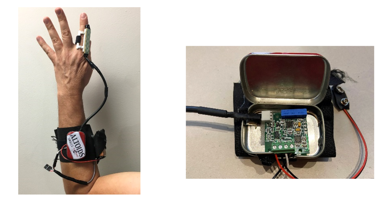
DCs performing adjustments were asked to wear a finger-mounted splint, built by the investigators, to measure forces associated with the thrusts (Figures 1A and 1B). The splint provided a rigid, flat surface for the pressure sensor to help prevent curvature or indentation of the sensor, which could distort measurements. It also guaranteed that the area of the splint was the only area of contact with the thrusting finger, so no force was exerted to the spine outside of the contact area of the sensor. The splint consisted of a 3D printed plastic frame, contoured on one side to fit over the doctor’s index finger, and affixed with a Velcro strap. A Tekscan Flexiforce pressure sensor (Tekscan, South Boston, MA, USA) was affixed to the flat outer face of the frame with 3mm thick poster-mounting tape. Two wires connected the pressure sensor to a Tekscan amplifier, which was contained within a tin enclosure and attached to the forearm with a wide Velcro strap, which also held a 9-volt battery to power the amplifier.

In phase 1, the amplifier was wired to a Noraxon Analog Input System module to convert the analog signal voltages into digital form, and then into the Noraxon MR3 software used also by the motion capture system (Noraxon, Scottsdale, Arizona, USA.) By the time of phase 2, our lab had acquired a Noraxon Ultium EMG system, which can receive a variety of types of input signals and shares the same software as the motion capture system. In both cases, the apparatus was shown and explained to the DCs, ahead of time.
Because the pressure sensor’s output signal is in millivolts (mV), it had to be calibrated by converting to Newtons (N) to determine force levels. To accomplish this: first, one of the investigators wore the finger-splint and pressed the sensor against a small wooden block placed on top of a force plate (Bertec model FP4550-08, Bertec Corporation, Columbus, OH), which we used as a gold standard for force calibration. In phase 1, the sensor was pressed for 10 press-release cycles, in 2 separate runs; in phase 2, an investigator pressed the sensor 9 times – 3 times with what he perceived to be a medium or “normal” amount of force, 3 times lightly, and 3 times with what he perceived to be a heavy amount of force. In both cases, mV levels from the pressure sensor were recorded by the Noraxon software while force levels from the plate were simultaneously recorded by the Bertec software. In phase 1, an investigator determined a conversion factor of calculated multiplier of 0.092 by comparing the separate sets of recordings; in phase 2, we used linear regression to determine a predictive equation (y = 0.0382x + 34.051).
We exported the force transducer and time channels from test recordings and used custom routines in Microsoft Excel to convert millivolts to Newtons of force using calibration factors, and to capture the peak force of each thrust.
RESULTS
For the larger motion capture study, 14 DCs associated with our university participated in the motion recordings of 23 supine SCAs, which took place in 9 separate sessions. The force sensor apparatus was available for only 6 of the 9 data collection sessions. Thus, we had 13 successful force recordings, for which the mV levels and calculated forces may be seen in Table 1. After mV to N conversions, we found peak forces ranging from 125.4 N to 46.8 N, with a mean of 79.5 N (SD 27.0).
The finger sensor and software remained the same for Phase 1 and Phase 2 recordings, but the hardware used to connect the sensor to the software was different and we used a different method of calibrating the finger sensor to the force plate. Thus, in Table 1 it may be seen that the numerical value ratios of the force values to mV values are different for Phase 1 than Phase 2. That is, with a simple multiplier the Phase 1 ratios are all 9.2% ‒ e.g., for Phase 1, record 1, 125.4/1363 = 0.092. For Phase 2, using a linear regression formula, the ratios range from 5.4% to 14.1%.
DISCUSSION
The peak force levels found in this study of supine cervical adjustments, with a mean of 79.5 N, are on the “light” end of what has been reported by other studies. The range of individual thrust values we found, from a maximum of 125.4 N to a minimum of 46.8 N, is roughly comparable to the mean values reported by Kawchuk26 (40.5 N, 102.2 N, and 109.8 N) and the resultant force levels of 108 N and 110 N reported by Van Zoest.27 But they are noticeably lower than the means reported by Wuest22 (200 N and 273 N), Symons23 (177 N to 332 N), and Gorrell28 (136 N to 407 N). Study-to-study comparison of the styles of HVLA procedures is difficult, but adjustments in our study were neither “rotation” or “lateral break” [rapid lateral flexion] maneuvers, as categorized by Kawchuk26 – rather, they typically involved both components.
The finger splint worked very well. No participants reported any discomfort, and doctors reported that the splint did not interfere with their ability to hold the contact point or deliver the thrust. We plan to use the Phase 2 system again for trials in which we will measure both force and motion of SCAs. Its main advantage is that the 2 systems can be integrated together in the Noraxon MR3 software and events can be analyzed in the same exported Excel file.
Limitations: How confident can we be that our determinations of force are valid? Perhaps not entirely. This type of pressure sensor, though in widespread use, needs a warm-up procedure prior to data recording, and we are not certain that the procedure was duplicated consistently in each session. In a world where people are accustomed to the sophistication of modern phone apps, it is important to understand that measurement of force levels during adjustment is not so straightforward. Calibration before each session helped ensure that sensor readings would be converted to force accurately, when conditions may have differed from day-to-day and between practitioners.
The finger splint, though very light, was needed to provide a stiff, flat surface against which to press the thin pressure sensor and render a true measure of force. It is possible the splint may have impacted the doctor’s ability to feel the segmental contact point, despite that no doctors admitted to it causing interference.
CONCLUSION
There had previously been a limited amount of investigation of the peak forces applied to patients’ necks during supine cervical adjustments. Our findings for 13 force recordings, in a range from 46.8 N to 125.4 N (mean 79.5 N) are comparable to, though on the lighter end of, previously reported values ranging from 40.5 N to 407 N. Our findings contribute additional evidence to the literature and will inform our future investigations of force applied during chiropractic adjustments.
ACKNOWLEDGMENT
Thank you to Andrea Jimenez for literature search assistance.
FUNDING SOURCES AND CONFLICTS OF INTEREST
The project was internally funded by Life University. The authors have no conflicts of interest to declare.