


Introduction
Leg length discrepancy is an important consideration for many chiropractic techniques when determining the appropriate adjusting procedure to utilize. Techniques such as Activator Methods and Thompson Technique employ “leg check” procedures to assess unilateral postural lower extremity deficiency, viewing discrepancies as an indicator and subsequent change as a post-check for the technique procedure employed. There are, however, several causes of unilateral postural lower extremity deficiency, and “its frequency in the population is likely to be at least 50% and probably as high as 80% in amounts of 3 mm or more” as noted by Lawrence1 and as much as 90% as reported by Knutson.2 Therefore, it is clinically relevant to the chiropractic profession.
Chiropractic techniques, such as the Gonstead method, also see the clinical significance of leg length discrepancies. Their evaluation, however, focuses on femoral head height that may be present and measured on the AP lumbopelvic x-ray.3,4
The chiropractic profession is not the only profession that assesses femur head height utilizing x-ray film analysis. Podiatrists also perform such assessments as an uneven femoral head height on an x-ray may cause compensatory mechanisms in gait resulting in ankle and foot disorders. Podiatrists employ similar assessment procedures to chiropractors. Both professions use a standing AP pelvic x-ray, which replicates weight-bearing conditions. Both note the difference in the femur head height and calculate the difference. Historically, rulers were used with plain film, but now digital tools are available for digital films. For podiatrists, a measured difference (MD) of more than 5 mm is considered clinically significant. In conjunction with a standard AP pelvis X-ray, podiatrists might also utilize a specialized X-ray technique referred to as a scanogram. A scanogram includes three separate X-rays of the hip, knee, and ankle joints to give a more precise measurement, as it includes the contributions of the femur and tibia to leg-length inequality.5,6
The causality dilemma exists because leg-length inequality can contribute to pelvic unleveling, and pelvic misalignment can affect leg-length inequality. Some Gonstead chiropractors utilize measured deficiency (MD) to calculate what is termed AD or actual deficiency to determine the contribution of pelvic misalignment to femur head height on the AP film.3,4 This is problematic as clinicians may take actions in a patient’s case that are not based on accurate information. The present study examines x-ray projection factors that may influence projected femur head levels and offers a mathematical method to calculate the change in femur head levels resulting from changes in these factors as seen on the AP radiographic view. This allows the clinician to be better informed as to the effects of various factors on the projection of femur head height levels.
DISCUSSION
There is a mathematical method to determine the difference between the projected femur head heights on the radiograph that is induced when the pelvis undergoes y-axis (axial) rotation on the anteroposterior radiograph.
Different factors used in this calculation have different effects. A: source-object distance, B: object-receptor distance, C: amount that source (central ray) is superior to the femur heads and D: axial rotation of the pelvis all contribute to the projected femur head height changes.
The effects of each of these can be illustrated.
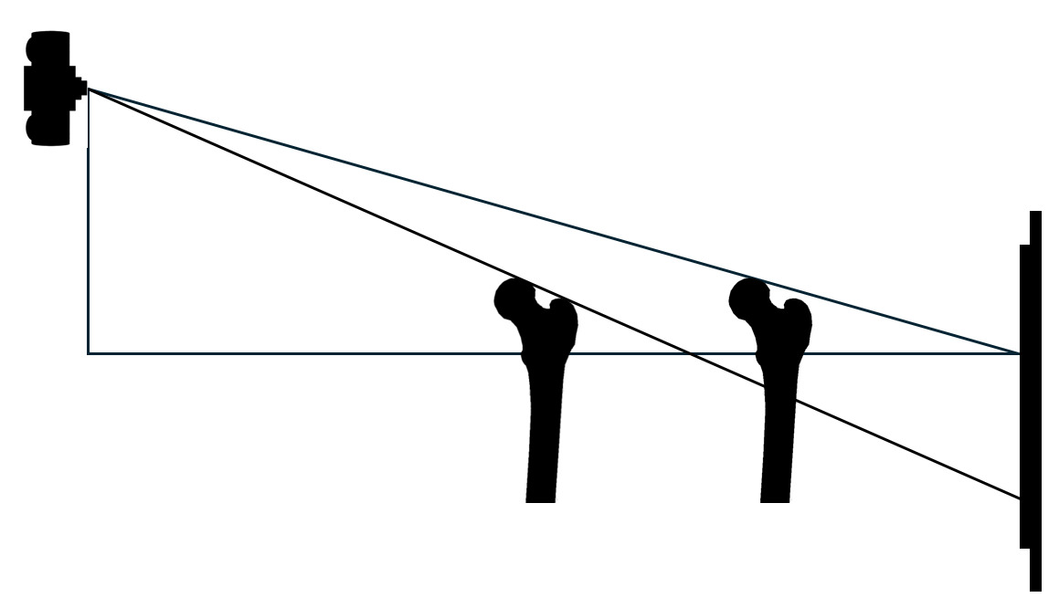
With the source above the level of the femur head, as the source-object distance is increased the femur head is projected higher on the radiograph. However, it will still be projected below the level of the femur head. This is shown in Figure 1.

With the source above the level of the femur head, as the object-receptor distance increases the femur head is projected lower on the radiograph as seen in Figure 2.
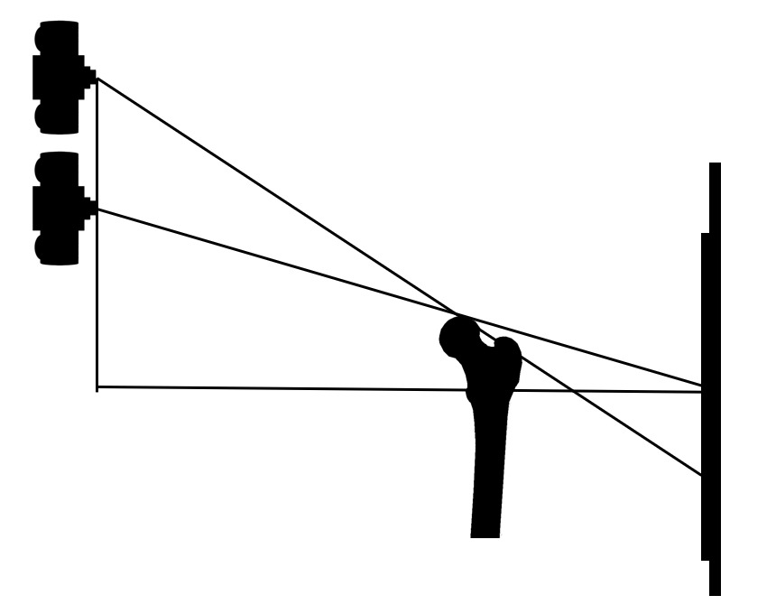
With the source above the level of the femur head, as the source is raised the femur head projects lower on the radiograph as seen in Figure 3.
In a superior to inferior view of a non-rotated pelvis the relationship of the iliums relative to the source and receptor can be shown as seen in Figure 4.

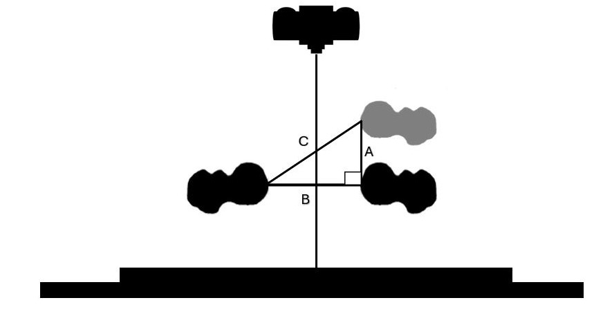
In a superior to inferior view, as the pelvis undergoes y-axis (axial) rotation when neither femur is fixed. One femur head moves toward the source, decreasing the source-object distance and increasing the object-receptor distance. The opposite femur moves toward the receptor decreasing the object-receptor distance and increasing the source-object distance. This is seen in Figure 5.
_rotation_when_neither_femur_is_fixed._one_femur_hea.png)
The amount these factors affect the projection of the level of 1 femur head relative to the other femur head can be calculated by the following process. We have chosen what we feel are plausible numbers based on our experience to represent the various factors but the numbers would vary depending on patient size and source-receptor distance, source height above the femur heads and pelvic axial rotation.
Calculating Femur Head Height Differences Due to Projection Error
Step 1: Determine true distance between the femur heads.
The distance between the femur heads (Fig 6) as measured on the radiograph is greater than the true distance due to magnification on the radiograph. Using the source-receptor distance and the source-object distance calculate the true distance between the femur heads on the radiograph as seen in the example.
_as_seen_on_the_anteroposterior_rad.png)
Example
-
Source-receptor distance: 1016mm (40")
-
Object-receptor distance: 100mm
-
Object-source distance 916mm
-
Distance between femur heads on the radiograph: 150mm
Using the formula for magnification: Source-receptor/source-object distance = magnification factor
1016/916 = 1.109 Magnification factor.
Distance between femur heads divided by the magnification factor.
150mm/1.109 = 135.257
The true distance between the femur heads in this example is 135.257mm.
Step 2: Axial rotation of the femur heads
Using a true distance between the femur heads 135.257mm rotate the pelvis 5 degrees with one side being fixed and the other side moving toward the source. The rotation of 1 side moving toward the source is done to model a patient who has been backed against the bucky so there is contact of the posterior side of the patient’s pelvis area to the bucky and the contact on one side is maintained when the pelvis is axially rotated. Therefore the pelvis must rotate toward the source on one side. When this is calculated it shows that side A = 11.833mm, side B = 135.257mm and Side C = 135.774mm.
The distance that one femur head will move forward toward the source in this example is 11.833mm as seen on side A. (Fig 7)
Note: The question may arise at this point as to how moving 1 femur head closer to the source will affect the magnification factor.
To see if this distance would affect the magnification factor this 11.833mm distance must be factored into the equation for magnification.
916mm source object distance when pelvis is not rotated – 11.833mm, which is the distance that the femur moved closer to the source when the pelvis is rotated 5 degrees = 904.167mm for the source-object distance for the rotated pelvis.
1016mm/904.167 = 1.124 Magnification factor compared to the magnification factor if using the non-rotated pelvis where the magnification factor is 1.109.
Distance between femur heads of 150mm/ 1.124 = 133.452mm for the rotated pelvis
This compares to 135.257mm which is obtained by using the non-rotated pelvis.
This gives us a difference of 135.257 – 133.452 = 1.805mm
Using the distance between the femur heads of 133.452mm, we will once again calculate the movement of the femur toward the source during 5 degrees of y-axis (axial) pelvic rotation. This gives us Side A = 11.676mm, Side B = 133.452mm, Side C = 133.962mm. The amount the femur now moves toward the source is Side A = 11.676mm. (Fig 8)

The difference in the movement of the femur head toward the source between when the non-rotated pelvis is used to set the magnification factor compared to when the rotated pelvis is used to set the magnification factor is 11.833mm – 11.676mm = 0.157mm. It should also be noted that we used a 90 degree angle for angle c during these pelvic rotation movements. This was done to more easily illustrate the movement. More precisely the movement is an arc and therefore the 11.676mm distance would be 11.642mm giving us a 0.191mm difference. These are both insignificant amounts in clinical practice and we will use the magnification factor and distance between the femur heads obtained in the non-rotated pelvic position.
We will continue our example using 135.257mm rounded to 135.3mm for the true distance between the femur heads and 11.833mm rounded to 11.8mm for the amount that the rotated pelvis moves the femur head closer to the source. For the source object distance for the non-rotated pelvis we have 1016mm source-receptor distance – 100mm object-receptor distance = 916mm for the source-object distance.
For the rotated pelvis we have 1016mm source-receptor distance – (100mm + 11.8mm = 111.8mm object-receptor distance ) = 1016mm source-receptor distance -111.8mm object-receptor distance = 904.2mm source-object distance.
Step 3: Non Rotated Pelvis
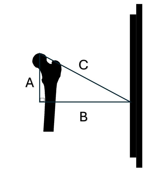
For our example we will select a source (tube height) placed 100mm above the femur head. For our examples we will use a 40" horizontal source-receptor distance and the following factors: Side A = 100mm (source height above the femur head). Side B = 916mm horizontal source object distance. (Source-receptor distance: 1016mm (40") - object-receptor distance: 100mm) = 916mm and angle c of 90 degrees we were able to calculate the following: Side C = 921.4mm, Angle a 6.23 degrees, Angle b 83.77degrees as shown in Figure 9.

-
Side A = 100mm (source height above the femur head)
-
Side B = 916mm horizontal source object distance
-
(Source-receptor distance: 1016mm (40") - object-receptor distance: 100mm) = 916mm
-
Side C = 921.4mm
-
Angle a 6.23 degrees
-
Angle b 83.77degrees
-
Angle c 90 degrees
Step 4: Non Rotated Pelvis
We know that side B is 100mm and angle c is 90 degrees. From the previous calculation we also know that angle b is 83.77 degrees. This allows us to calculate that:
Side A = 10.92mm (Projected distance of the femur head on the radiograph below the actual height of the femur head.), side C = 100.59mm, and angle a 6.23 degrees. These are shown in Figure 10.
-
Side A = 10.92mm (Projected distance of the femur head on the radiograph below the actual height of the femur head.)
-
Side B = Horizontal object-receptor distance = 100mm
-
Side C = 100.59mm
-
Angle a 6.23 degrees
-
Angle b 83.77 degrees
-
Angle c 90 degrees
The difference in side A of 10.92mm in this non-rotated pelvis compared to side A when the pelvis is rotated will give us the difference between the projected femur head heights on the radiograph
Step 5: Rotated Pelvis (pelvis rotated 5 degrees)
With the source positioned 100mm above the level of the femur head for side A.
A source-object distance of 904.2 mm [1016mm – (100mm + 11.8mm) = 904.2mm] when 135.3mm distance between the femur heads as measured on the radiograph is rotated 5 degrees) for side B and an angle c of 90 degrees this allows us to calculate that: Side C = 909.7mm, angle a = 6.3 degrees and angle b = 83.7 degrees as shown in Figure 11.

-
Side A = 100mm (source height above the femur head)
-
Side B = 904.2mm horizontal source object distance
-
Side C = 909.7mm
-
Angle a 6.3 degrees
-
Angle b 83.7 degrees
-
Angle c 90 degrees
Step 6: Rotated Pelvis (pelvis rotated 5 degrees)
We know that side B is 111.8mm and angle c is 90 degrees. From the previous calculation we also know that angle b is 83.7 degrees. This allows us to calculate that: Side A = 12.34mm (Projected distance of the femur head on the radiograph below the actual height of the femur head.), side C is 112.479mm and angle a is 6.3 degrees. This is shown in Figure 12.

-
Side A = 12.34mm (Projected distance of the femur head on the radiograph below the actual height of the femur head.)
-
Side B = 111.8mm
-
Side C = 112.479 mm
-
Angle a 6.3 degrees
-
Angle b 83.7 degrees
-
Angle c 90 degrees
Step 6
Using the difference in femur head levels on the radiographs in the rotated and non-rotated positions we have 12.34mm – 10.92 = 1.42mm
In this instance there was a 1.42mm difference in projected femur head height level due to pelvic rotation of 5 degrees as seen on the radiograph.
It should be noted that if the pelvis is rotated on the y-axis (axial rotation) and there is also a femur head height difference then the amount that the rotation contributes to the difference in femur head heights can be determined and used along with the amount seen on the radiograph to give the amount of difference in femur head height levels that would be found without the rotation. Additionally, if the clinician needs to know the actual difference in femur head heights then the difference determined on the radiograph after axial rotation is taken into consideration can be divided by the magnification factor that is applicable in that particular case to give a true femur head height difference.
Obviously we cannot include all the possible source-receptor distances, object-receptor distances, source heights above the femur heads and pelvic rotations (i.e. femur head movement on one side closer to the source) in our example. But the clinician can select some general examples from among their own patients and by applying these methods determine how much different factors are contributing to any femur head height differences. When evaluating any structure an understanding of the limitations of the measuring methods is important. Merely measuring the relative femur head heights on a radiograph does not give the clinician a true measurement of the actual difference between the levels of the respective femur heads. Better understanding the effects of projection and the errors it can create will better inform the clinician as to the accuracy of what they are viewing on a particular radiograph. Clinicians should endeavor to gain as much information from every test as is possible and an understanding of the magnitude of the effects, be they large or small, that projection error produces is an important clinical skill.
Axial rotation can introduce confounders into the analysis process.7–9 This method may be of assistance in improving insights into the effects that projection can cause when seeking to determine differences in femur head levels. There are two obvious weaknesses in this article. One is that we have used the horizontal distance between the source-object and object-receptor when technically we should have used the diagonal distances when calculating magnification. This was done for a reason. Clinicians seeking to produce a 14"x17" antero-posterior lumbo-pelvic radiograph at a 40" source-receptor distance move the tube stand 40" (1016mm) from the receptor. As this is an article for clinicians we felt that this was the best way to present it and the magnification factors are the same regardless of whether you use the diagonal or the horizontal distances but we felt we should point it out. Another obvious weakness in this article is that there is no method presented for calculating the rotation of the pelvis. If the pelvis is not rotated or only slightly rotated that can probably be determined by a viewing of the radiograph. But for larger or less easily determined degrees of axial pelvic rotation it may be necessary to utilize other methods. A proposed mathematical method to determine pelvic rotation has been published.7 In addition a computer application to aid in the needed computations has been developed by Derek A. Lopes and is available free of charge at https://www.gonstead.com/pelvic-rotation-calculator-app/ These are both undergoing further study but the results have not yet been published. In the mean time understanding the effects of projection error can give the clinician a better understanding of various factors affecting measured femur head height on the anteroposterior pelvis as seen on radiographs.
Other questions may arise. Why have we taken our calculations out to 1/1000 of a millimeter in some instances. Certainly this type of accuracy cannot be achieved in a clinical setting. Additionally, we do not mean to suggest that this degree of accuracy is necessary to good care; in fact, we believe just the opposite. However, it does serve to show that this type of measurement can be carried out in great precision in models and give the clinician and researcher a more complete understanding of the abilities to calculate projection error. Also there are many guidelines related to many different subjects as to when some action needs to be considered in clinical care. In the chiropractic setting some clinicians may use a difference of 7mm to be a point where a lift may be indicated.10 If the case is very close to that difference a more accurate calculation may be of interest to the clinician. For whatever reason the more complete the knowledge of projection error the better for both clinicians and patients and the clinician should look at this as a tool to be integrated when and as appropriate.
We firmly feel that the first efforts of the clinician should be to affect proper X-ray machine alignment followed by careful patient placement in order to avoid as much as possible projected axial rotation and the resulting projected femur head height changes. Wall has noted that X-ray machine malalignment can create projection error.11 X-ray machine alignment and patient placement are the first line of defense for the clinician in preventing femur head height radiographic changes due to projected axial rotation. While X-ray machine alignment problems can and should be determined in advance, patient positioning errors in a busy clinical setting will likely occur even with the best of care and an understating of the effect of rotation provided by this article is important. When this study is coupled with studies already conducted and studies yet to come a more accurate picture of the effects of projection error will be better understood allowing for a more accurate use of this diagnostic tool by the clinician.
Conclusion
This article presents a method for the clinician to better understand the confounding effect that various factors may cause on the radiograph when attempting to measure relative femur head heights. A method to more accurately understand the magnitude of the difference of one femur head height compared to the other femur head height will give the clinician a better idea of what is occurring in an individual patient. Clinicians should understand the confounding factors affecting tests that they utilize. This article represents one more step in allowing the better understanding of a tool that is used in clinical practice.