


INTRODUCTION
The performance of a manual adjustment (or manipulation, or high-velocity, low-amplitude manual thrust) by a chiropractor is a complex skill1 that requires high levels of sensory & motor coordination,2 and deliberate practice to achieve a high level of expertise.3 Exactly what characteristics define an expert practitioner are uncertain, but several studies have identified differences in force components between chiropractic students and experienced chiropractors (Doctors of Chiropractic or DCs), such as pre-load force, time-to-peak (impulse duration), peak force, and rate of force delivery.1,4,5
However, while there are a number of sources of information about the force characteristics of chiropractic adjustments, there have been just a few studies of the movement characteristics of DCs and other doctors and therapists who practice manipulation.6 Lorme7 measured motion ranges and velocity with a Lumbar Motion Monitor during chiropractic manipulation and used a 35-mm camera to take still photos in the frontal and sagittal planes. Gelly8 affixed a wireless tri-axial accelerometer to the dorsum of a chiropractor’s hand to record hand acceleration amplitude and latency values during manipulation. Maiers9 calculated peak velocities and accelerations of hand movement during performance of thoracic thrusts on a mannequin by having participants wear an inertial motion unit on the left hand. In the process of calculating lumbar contact force during side-posture manipulation, Myers10 outfitted a DC with reflective markers for motion capture but did not report the motion data. Weiner11 and Russell12 used a motion capture system to examine spinal and extremity movements during performance of chiropractic lumbar side-posture adjustments. Derian13 used an optical motion capture system and a pair of force plates to examine pelvic kinematics of physical therapists performing side-lying manipulation. But there is little published information beyond these examples.
The report below is part of a larger effort to document and analyze kinematic and kinetic characteristics of chiropractic adjustments. In this current project, we have used the case of a single participant as a vehicle in development of analysis methods and decisions on what data to report and how to communicate it. We intend the results to help advance discussion about how adjustments and manipulations are performed and assessed, by supplementing subjective opinions and qualitative observations with objective measurements. The data and structure of the report may be most informative to chiropractic educators and students and will contribute to an overall understanding of how DCs perform adjustments.
METHODS
At the time of data collection, the participant of this study was a senior-year student in the Doctor of Chiropractic program at Life University and enrolled in an elective biomechanics class, which included an introduction to our university’s motion capture system. He volunteered to be recorded while performing supine cervical adjustment thrusts on a mannequin specifically designed for palpation and adjustment education, called a Palpation and Adjustment Trainer (PAT).14,15 Later, as a practicing DC, he agreed to the use of his data and assisted with interpretation.
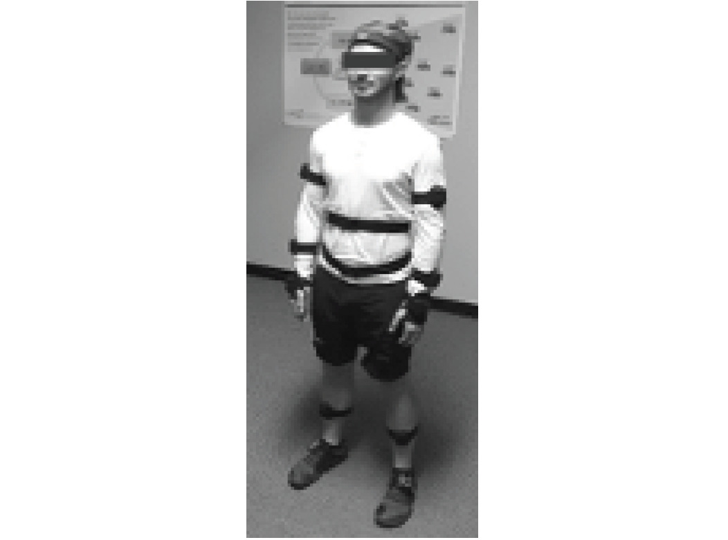
The participant was outfitted in a full-body profile of 16 inertial measurement units (IMUs; Myomotion system, Noraxon; Scottsdale, Arizona), using Velcro straps and double-stick tape, with IMUs overlying the hands, forearms, upper arms, head, the T1 and T12 vertebrae, the sacrum, and the thighs, lower legs, and feet. The IMUs contain accelerometers, gyroscopes, and magnetometers and are able to measure angular displacement, velocity, and orientation. The proprietary software (MR 3.6, Noraxon; Scottsdale, Arizona) provides for clinical use of IMUs as electronic inclinometers to continuously track spinal and extremity movements. Once the IMUs were placed, calibration was performed while the participant stood in a neutral position (“anatomical position” except with the thumbs forward) for 30 seconds for the software to define zero points for each plane of motion (Figure 1).
The participant was then asked to perform 3 “Supine Cervical Set” adjustment thrusts,16 which, at our institution, is understood to begin by standing superior to the patient’s head and identifying the desired location; then stepping to 1 side, laterally flexing the patients’ neck is to the ipsilateral side and rotating the head to the contralateral side; and then delivering a thrust. Only the final recording was selected for analysis, with the first 2 thrusts treated as practice attempts.
The Noraxon software allows for viewing of recorded motion by generating an “avatar” video from the data (still images, Figure 2). An advantage of watching the avatar video within the Noraxon software is that motions can be viewed from any angle, which can be changed at will. Avatar videos can be exported as video files with selected fixed viewing angles.
The principal author identified the moments of maximum pre-thrust set-up and the peak of thrust by examining the video within the Noraxon software several times at a slow playback speed. The peak of thrust was identified as the time when multiple body segments appeared to have reached a maximum coordinated thrust. The recording was then exported in 5 versions from multiple viewing angles, with the beginning of the session viewed from the anterior, posterior, left, right, and above (still images, Figure 2); these were later merged into a continuous sequence using Camtasia software (TechSmith, East Lansing, Michigan, USA.) The 5-view video was examined by other members of our research team, 1 of whom is an experienced technique instructor, and who verified that the performance was representative of how the maneuver is taught at our institution. The authors each separately examined the 5-view video and independently wrote impressions of the actions, which were later merged and edited.
Data were exported to Excel .csv files for 37 distinct motions patterns: flexion-extension, lateral bending, and axial rotation of the cervical, thoracic, and lumbar spinal regions; flexion-extension, abduction-adduction, and internal-external rotation of the shoulders and hips; flexion-extension of the elbows and knees; flexion-extension, radial-ulnar deviation, and pronation-supination of the wrists; and dorsi-plantarflexion, adduction-abduction, and pronation-supination of the ankles. All motions were graphed, and the graphs were inspected for obvious errors in recording – e.g., graphic spikes depicting anatomically implausible motions may indicate an IMU was too loosely attached or knocked askew. Data values were then extracted for each spinal region or extremity segment and plane of motion, corresponding to the times of maximum pre-thrust set-up and the peak of thrust.
Results
The selected participant file had no apparent evidence of recording errors, and all values were assumed to be valid. A complete list of spinal regional and extremity segmental motions may be seen in Tables 1, 2, and 3 below, organized by region, plane of motion, measured position at the peak of pre-thrust set-up (“set-up”), measured position at the peak of application of the thrust (“thrust peak”), and the amount of change between the 2 positions. One can also note how positive and negative numbers relate to directions of motion. The Table results may also be seen below, in Figures 3 through 9, and may be compared against their corresponding table values. In the tables, the changes between the positions of set-up and peak represent the amount of movement occurring during thrust. For example, it can be seen in Table 3 that the left ankle was in 30.2° of dorsiflexion at set-up (although that would seem to exceed the anatomical limit) and 30.2° at peak thrust, representing 0° of change. The largest amount of movement we recorded was a 12.7° decrease in pronation of the left wrist. On the assumption that discussion should focus more on larger movements, for purposes of interpretation we made a post hoc decision to use the mean of the absolute values of change for all motions (which was 2.5°) as a dividing line between “larger” and “smaller” motions and to regard change values of less than 1° as “negligible”. Thus, we considered change in absolute values from 1° to less than 2.5° as “small” and change of 2.5° or more as “larger”. Of 37 change values, 12 were negligible, 13 were small, and 12 were larger. More about our considerations may be found below in the Discussion.
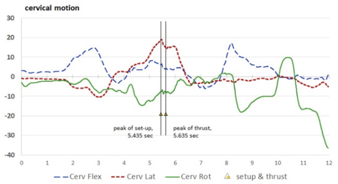
For orientation, consider the cervical motions in Table 1. From a neutral standing position, the cervical region flexed to 6.1° at set-up and then decreased in flexion by 1.9° (the negative change in position indicates an extension movement) to 4.2° at thrust peak. The largest cervical motion occurred in cervical lateral bending, which was 18.8° to the right (positive number) at set-up and moved toward neutral (“unbent”) during the thrust, ending at 14.4° of right lateral bending. At set-up, the participant’s cervical region was in 7.6° of left rotation (−7.6°) and minimally moved further into left rotation during the thrust (by −0.2°, to −7.9°).
_(cervical)___figure_3b_.png)
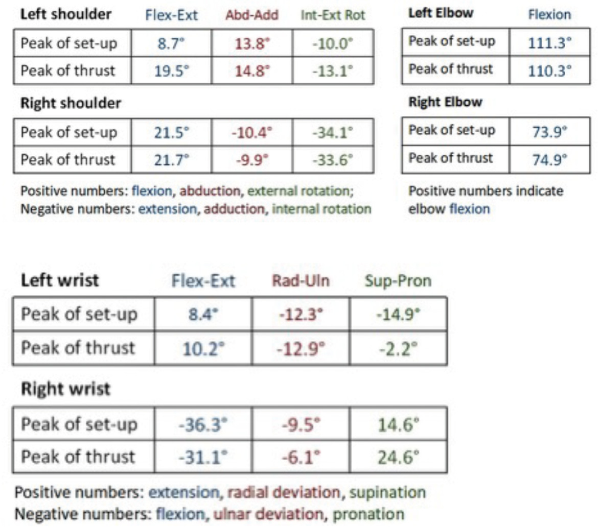
Most motions occurring during the thrust were small or negligible. For the upper extremities, larger movements included the left shoulder, which flexed an additional 10.8° during the thrust (from 8.7° to 19.5°) and internally rotated by an additional 3.1° (from –10.0° to –13.1°).
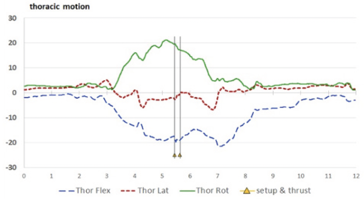
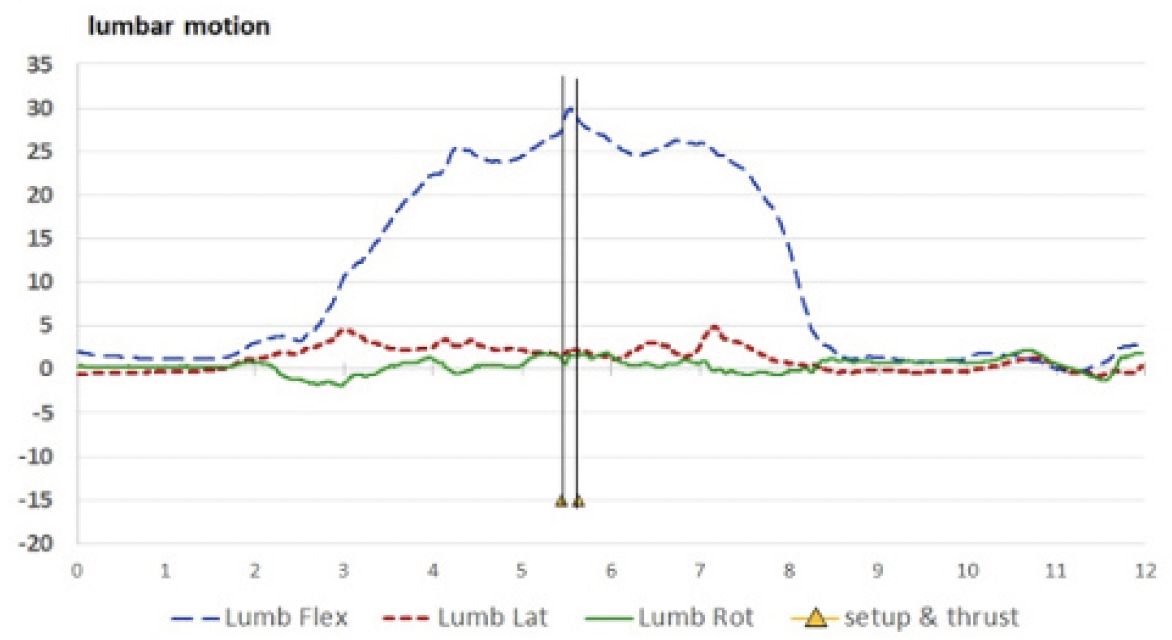
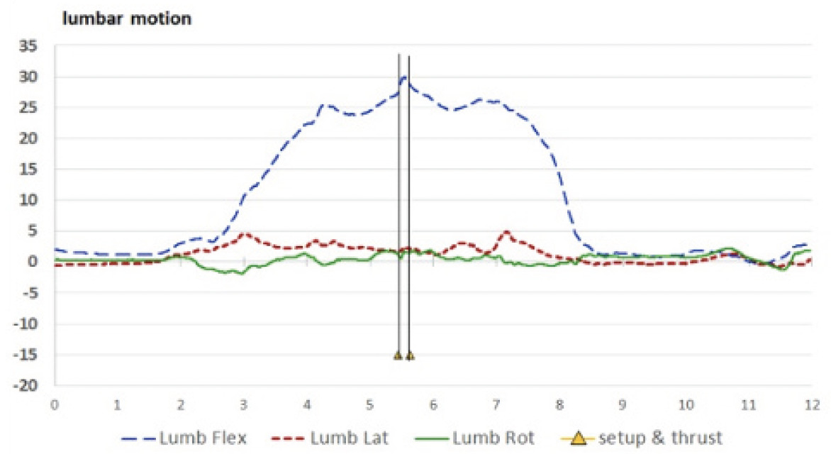
Spine: Spinal motions may be seen in Figures 3A (cervical), 3B (thoracic), and 3C (lumbar), with the entire period of recording included.

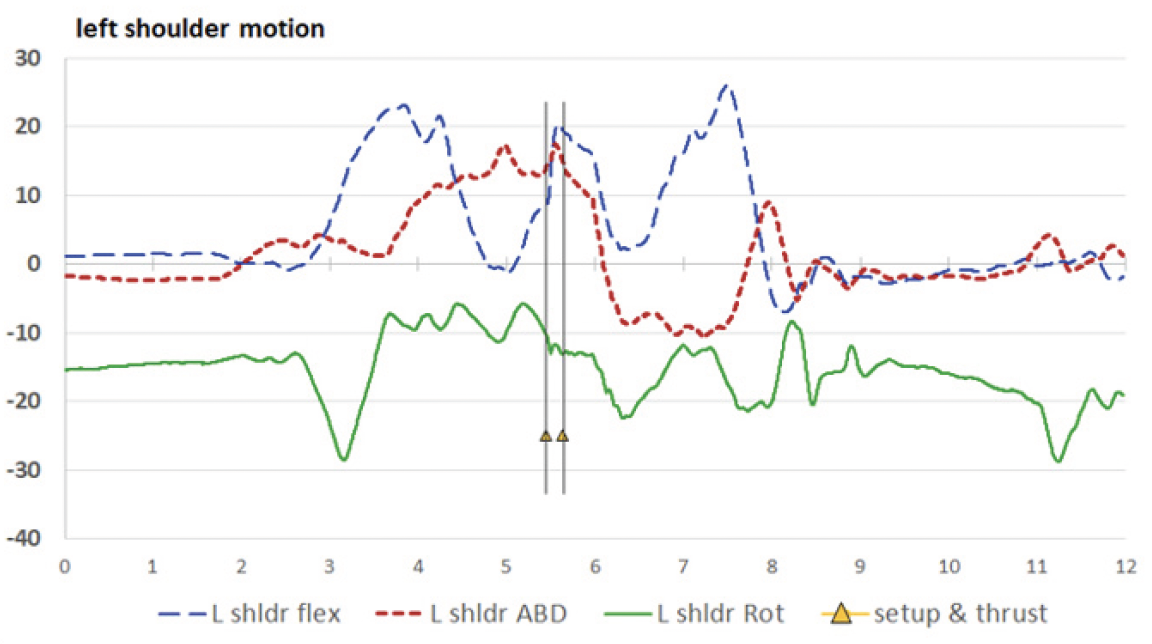
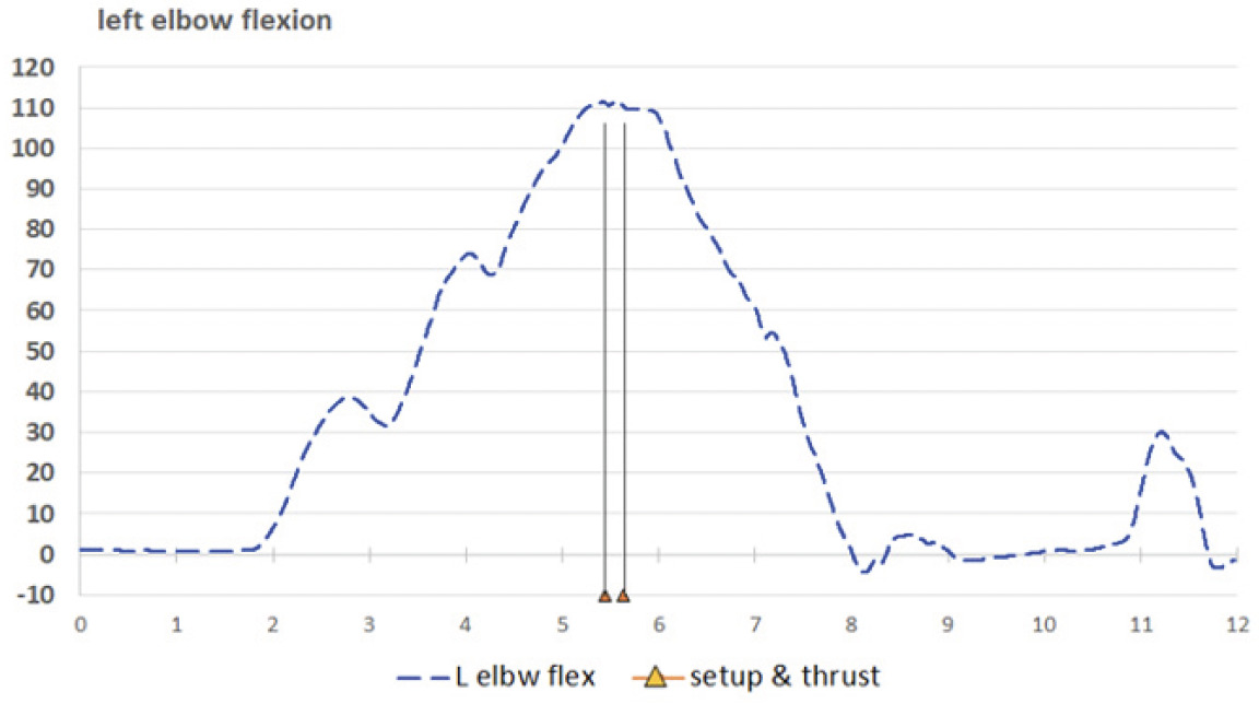
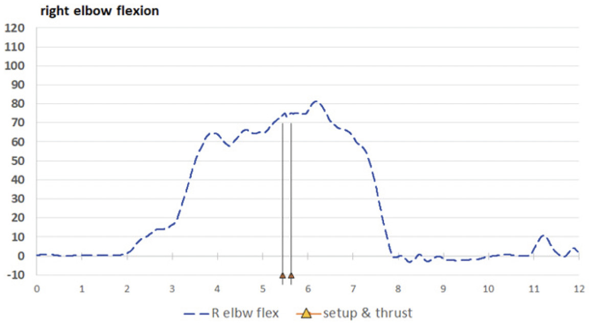
Upper extremities: Table 2 displays values for the shoulder, elbows, and wrists, and may be compared to Figures 4A and 4B (left and right shoulders), 5A and 5B (left and right elbows), and 6A and 6B (left and right wrists).


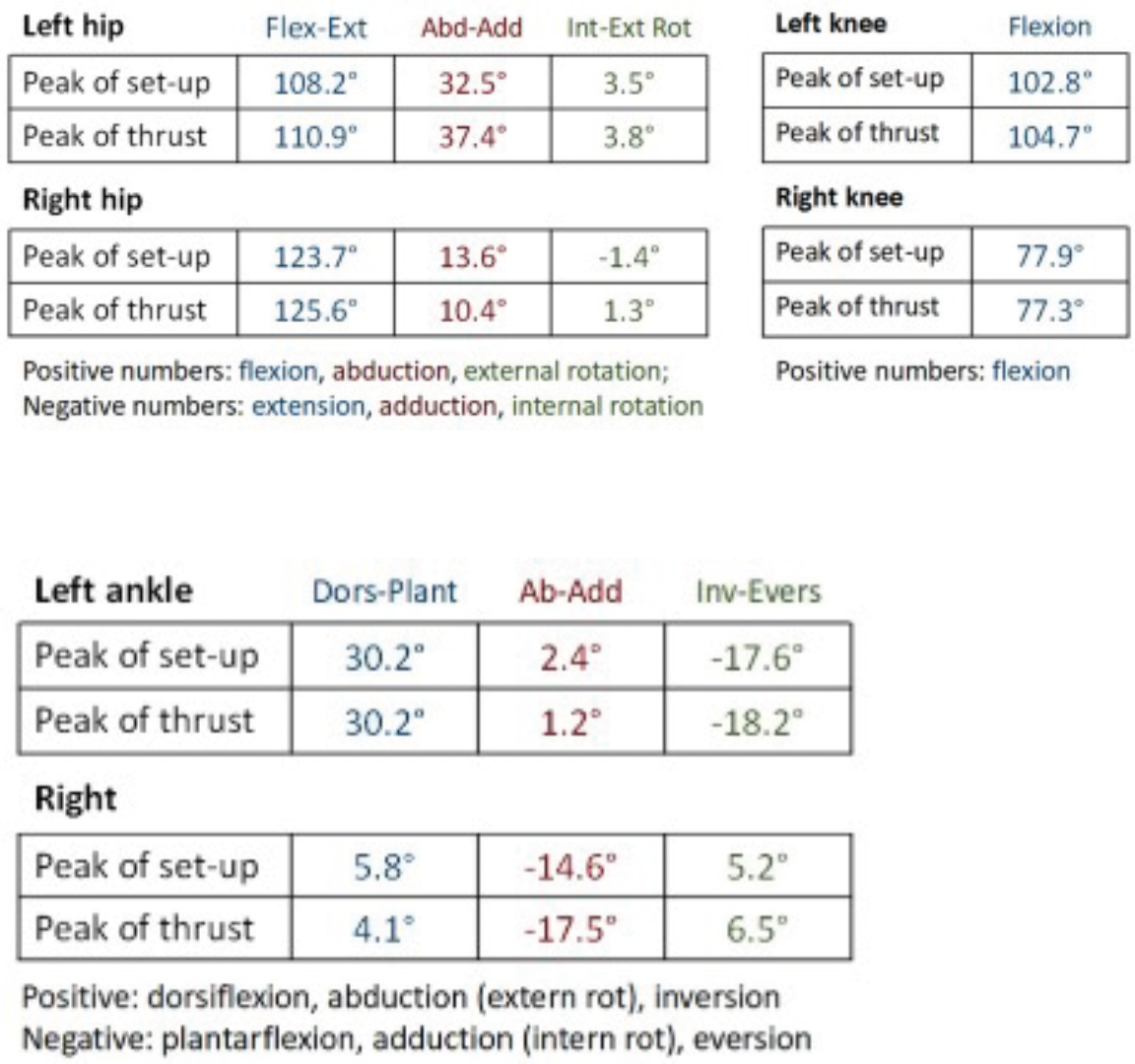
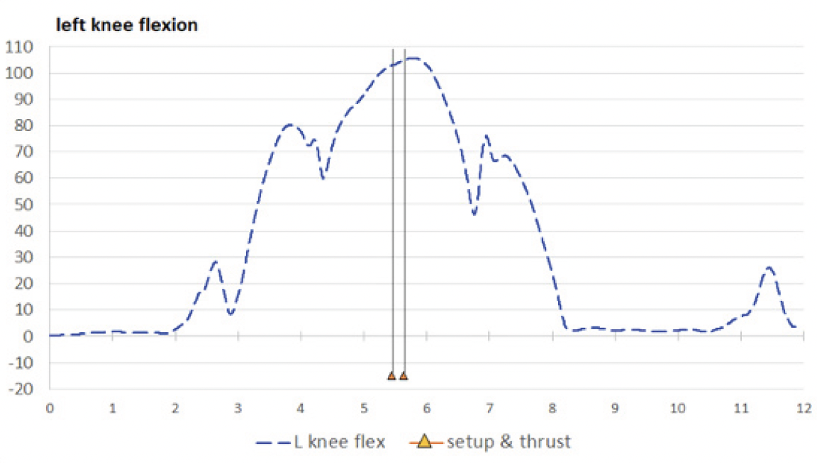
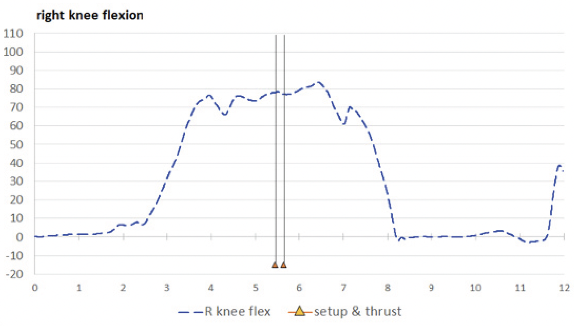
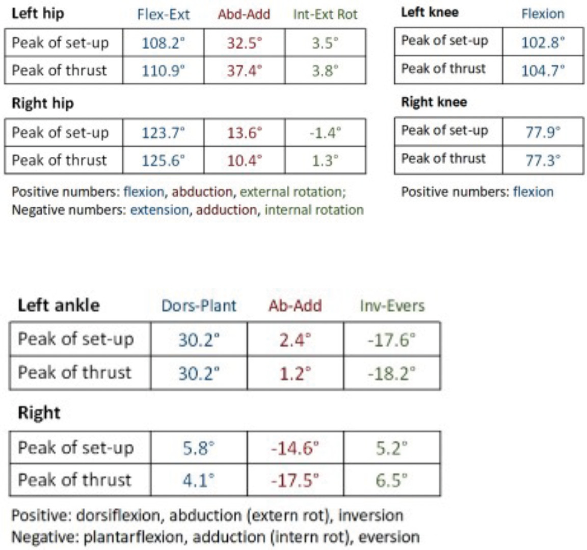
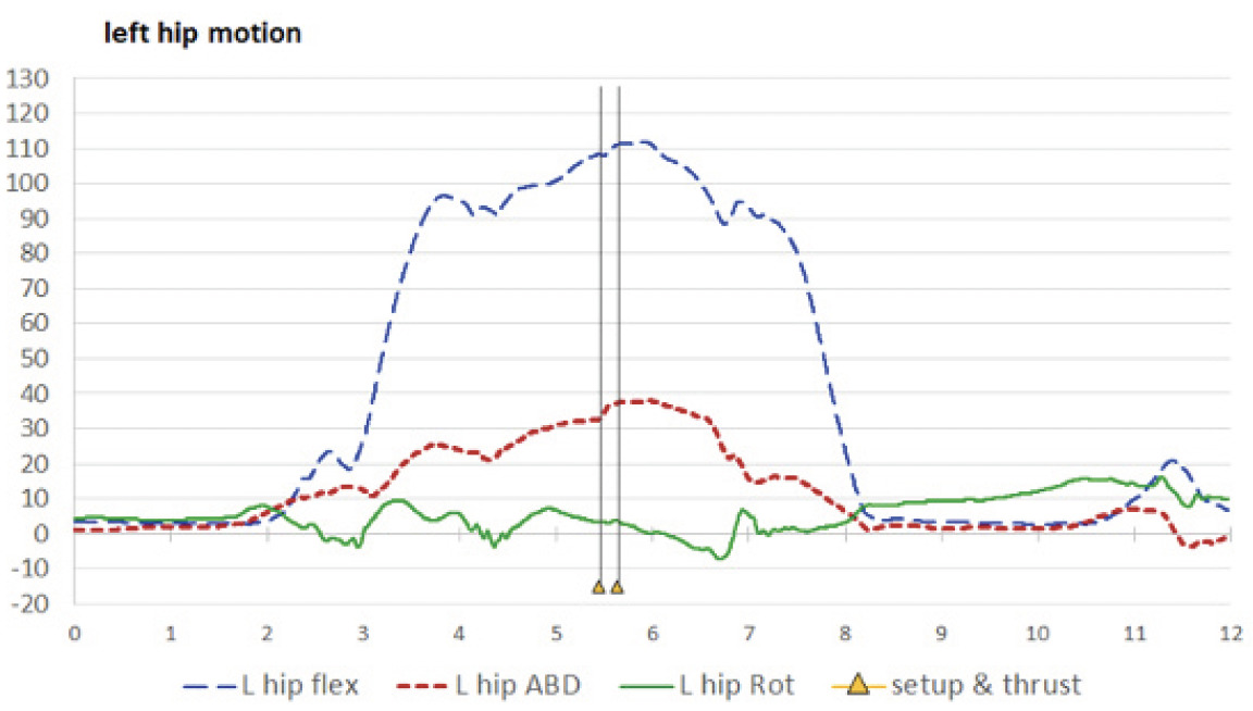
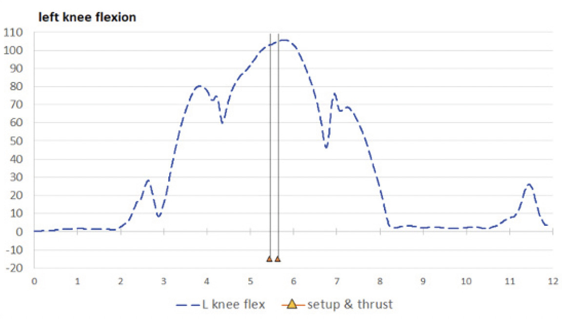
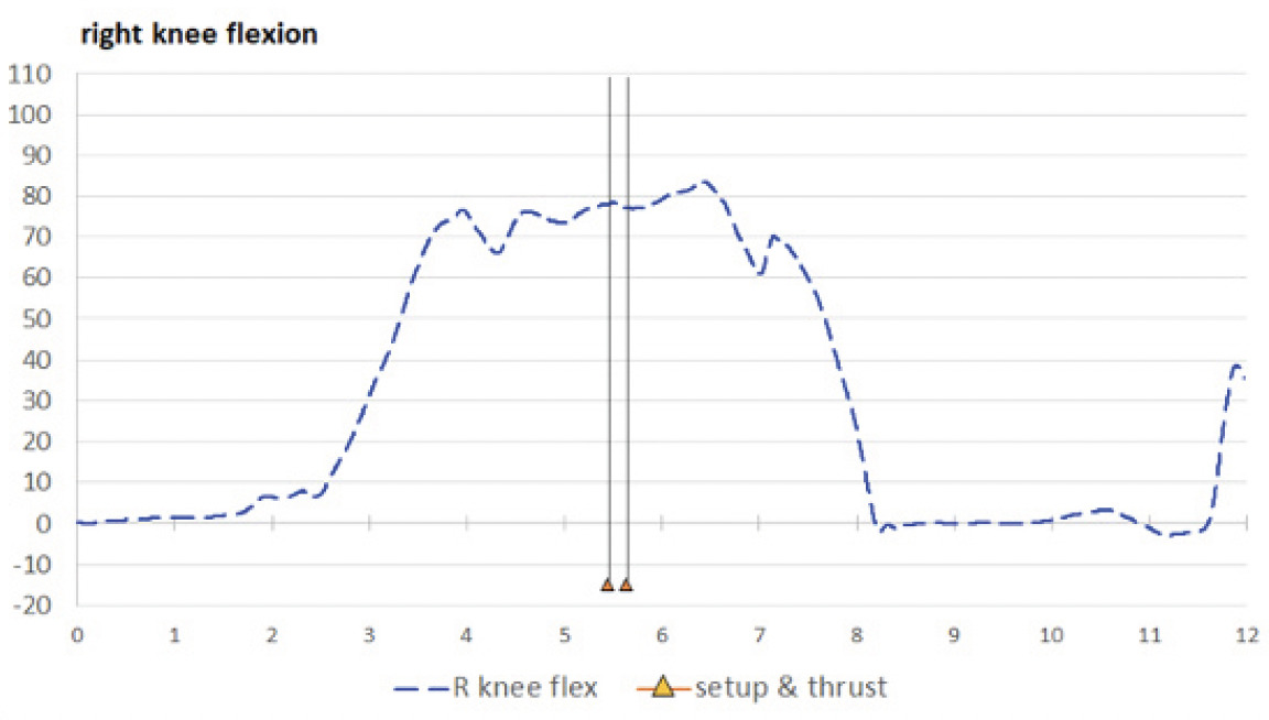
Lower extremities: Table 3 displays values for the hips, knees, and ankles, and may be compared to Figures 7A and 7B (left and right hips), 8A and 8B (left and right knees), and 9A and 9B (left and right ankles).


Observations by both authors, with comparisons to IMU data: The skeletal avatar video is a relatively low-quality computer animation and lacks some movement details. Spine movements are measured as cervical, thoracic, and lumbar regional blocks without intersegmental movement, and the ribcage is depicted as fixed with the thoracic spine. The hands and feet are measured as solid blocks that move at the wrists and ankles. In viewing and interpreting movements as seen in the avatar video, Author 2, the participant and originally the student, offered mostly qualitative observations and comments from a self-assessment perspective; Author 1, originally the class instructor, also offered qualitative observations and attempted some quantitative estimates of angular positions.
Many general observations were clear and indisputable. Beginning in an anatomical neutral position, the participant first shifted his weight to the right foot, picked up his left foot, and stepped to the left side. He bilaterally flexed his knees and hips as he moved to a squatted position. He flexed his elbows bilaterally and moved both wrists into ulnar deviation as he positioned his hands on the patient’s head and neck. He then picked up his left foot again, stepped a little further to the left and then squatted further, such that his pelvis was almost to the level of his knees. In comparison to the starting position, his set-up position was facing obliquely to the right. Author 2 described this final position as necessary for the left forearm to provide a thrust posterior-to-anterior, inferior-to-superior, and left-to-right to the target spinal segment.
Spine (Table 1 and Figures (3A, 3B, and 3C): In performing the thrust, the participant intended there to be little change in spinal orientation as he moved to a squatted position. Based on the video, Author 1 perceived the lumbar region to be in flexion by the time of set-up, but was unable to estimate an angular value; and both authors perceived the lumbar and thoracic regions as laterally flexed to the right and rotated to the right. Viewing of the cervical region was difficult in all but the top view, in which it also appeared to be laterally flexed to the right and rotated to the right. According to the spinal IMU findings, the lumbar region was flexed to 27.3° at the time of pre-thrust set-up, but with very little lateral bending or rotation, and the thoracic region was in −17.6° of extension (which, to remain in an upright orientation, would be a necessary compensation to lumbar flexion.) The thoracic region was also in a small amount of left lateral bending (−2.5°) and a substantial amount of right rotation (19.5°). The cervical region was flexed (6.1°) and laterally bent to the right (18.8°) and was actually rotated to the left (−7.6°, relative to the thoracic region below it). Spinal positional changes during the thrust were small or minimal, with the exception of cervical lateral bending moving −4.3° toward neutral (“unbending”).
Shoulders (Table 2 and Figures 4A and 4B): Author 2 stated his opinion that the perfectly-executed thrust should have little movement of the elbow and shoulder, which should be kept as close to the body as possible, but that the thrust should come from the movement of the torso. At set-up, both authors recognized in the video that both shoulders were flexed just before the thrust, but the first author’s shoulder flexion estimates (left 20-40° and right 40°) were much higher than the IMU values (left 8.7° and right 21.5°). The IMUs found the left shoulder to flex further to the peak of thrust (to 19.5°), with negligible change for the right shoulder. Author 1 perceived the left shoulder to have 10° of abduction and –20° of internal rotation at set-up (actual IMU values: 13.8° and –10.0°, respectively), with slight increases during thrust (to 14.8° of abduction and –13.1° of internal rotation). Right shoulder abduction-adduction and external-internal rotation were not clearly visible in the videos.
Elbows (Table 2 and Figures 5A and 5B): Author 1 estimated the left elbow to be at an acute angle of 105° to 115° at set-up and the right elbow to be flexed at a “slightly obtuse” angle (i.e., less than 90°). These were not far off the mark, according to the IMUs (left 111.3°, right 73.9°). However, Author 1 perceived posterior-to-anterior linear translation of the left forearm as the “dominant visible motion” during the thrust, i.e., moving further toward extension, in coordination with the additional left shoulder flexion. While Author 1 perceived the left elbow to extend nearly 15° during the thrust, the IMUs found left elbow to extend only 1°.
Forearms and wrists (Table 2 and Figures 6A and 6B): Author 1 did not feel confident in making any visual interpretation of forearm pronation-supination, nor of the wrist motions flexion-extension and radial-ulnar deviation. Author 2 described his method as pronating the left forearm to contact the segment to be adjusted, with additional pronation of the forearm to provide a slight rotational component during the thrust. According to the IMUs, the left forearm was moderately pronated at set-up (–14.9°) and underwent a supination movement to have decreased pronation at thrust peak (–2.2°). The right forearm was moderately supinated at set-up (14.6°) and supinated further to the peak of thrust (24.6°). At set-up the left wrist was slightly flexed (8.4°) and in ulnar deviation (–12.3°); at peak of thrust there was only a small increase in flexion (to 10.2°) and negligible change in ulnar deviation (–12.9°). At set-up the right wrist was substantially extended (–36.3°), with a small amount of ulnar deviation (–9.5°); both extension and ulnar deviation showed small decreases at the peak of thrust (to –31.1° and –6.1°, respectively).
Hips (Table 3 and Figures 7A and 7B): Just before the thrust, Author 1 perceived the left hip to be flexed approximately 100°, horizontally abducted possibly 30-40°, and externally rotated possibly 10-20°. For the right hip, he estimated flexion to be 100-120°; judged that horizontal abduction was less than for the left hip but was unable to place a value on it; and was unable to see any amount of rotation. The estimates were consistent with the IMU values for flexion (left 108.2, right 123.7°) and horizontal abduction (left 32.5°, right 13.6°). According to the IMUs, left external rotation was only 3.5° and the right hip was internally rotated by only –1.4°. When the thrust was performed, it appeared that there were small increases in flexion of the hips, and the pelvis appeared to be oriented further toward the right – that is, a small increase in horizontal abduction for the left hip (to 37.4°) and a small decrease for the right hip (to 10.4°). There was negligible change in rotation for the left hip, while the right hip underwent a small amount of external rotation (to 1.3°).
Knees (Table 3 and Figures 8A and 8B): Just before the thrust the left knee appeared to be in an acute angle, flexed to possibly 95-100°, and the right knee to between 80-100°; there appeared to be minimal movement of the knees when the thrust was performed. The left estimates were not far off from the IMU values but were high for the right knee.
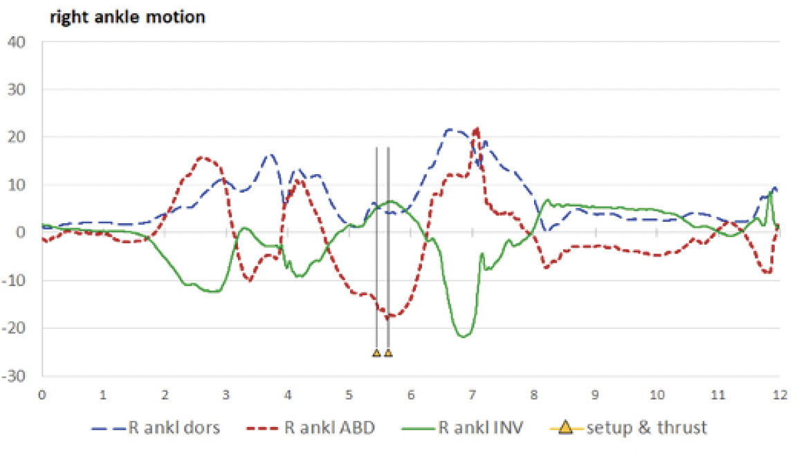
Ankles (Table 3 and Figures 9A and 9B): Author 2 perceived the ankles to be in dorsiflexion just before the thrust; Author 1 estimated the left ankle to be in 30° of dorsiflexion and the right ankle to be in a neutral position, with no further movement visible during the thrust for either side. The IMUs reported 30.2° of dorsiflexion the left ankle, with no change at thrust; and 5.8° of dorsiflexion the right ankle at set-up, slightly decreasing to 4.1° at thrust.
Ankle abduction-adduction and inversion-eversion seemed impossible to visualize in the videos. The IMUs reported a small amount of abduction for the left ankle at set-up (2.4°), with a small decrease at the peak of thrust (to 1.2°); and what might be considered a substantial amount of adduction for the right ankle at set-up (–14.6°), increasing to –17.5° at the peak of thrust. The left ankle was everted to –17.6° at set-up, with a negligible increase during the thrust; the right ankle was inverted 5.2° at set-up, with a small increase (to 6.5°) at the time of thrust.
DISCUSSION
For the authors, this report represents a step forward in our efforts to document and analyze kinematic characteristics of chiropractic adjustments. The positional findings may be important, as well, but are not a directive of how things should be done. Further discussion within the chiropractic profession and other manual therapy disciplines may determine which of our measures are most important or what others should be reported.
We are unaware of any previous, similar assessment of this type and the details may only seem relevant to a small slice of the chiropractic profession. Such objective study of the movements that practitioners’ bodies undergo during adjustment performance could have impacts on chiropractic education. Chiropractic students at our institution are traditionally taught how to perform adjustments largely by imitating postures demonstrated by an instructor17; often guided by standardized instructions from textbooks or manuals,16,18 on hand placement, arm position, pre-thrust positioning of patient, and intended direction of thrust. Early in the program, student assessment of adjustive technique mainly consists of qualitative judgement of their postures for specific technique methods and their ability to memorize details. Later in the program they are judged on performance of actual thrusts on patients – however, their performance is still judged qualitatively. While instructors who assess students’ technical performance are licensed and experienced chiropractors (Doctor of Chiropractic, or DC), they themselves learned by the same process. The cycle of education often lacks input from formal, kinematic analysis.
The performance of an adjustment is a labor-intensive activity, involving physical exertion and forceful repetitions, sometimes in awkward postures,7,19–21 and the performance of manual adjustment has some association with injury for DCs and DC students.19,21–26 The ability to objectively assess the postures and movement patterns employed by DCs during adjustment, and a better understanding of them, may have work injury prevention applications and could contribute to a better understanding of how DCs should or should not perform adjustments.
For the purposes of examining body motions and postural positions of DCs performing adjustments, the motion capture approach used in this study offers some advantages. While conventional video recording would allow for capture and review of adjustment performance (an event that happens quickly and may not be perfectly repeatable), motion capture allows for precise analysis. The multi-view option of the avatar video may provide insights for important features that the single viewpoint of conventional video may miss. However, both observers were wrong on some or their interpretations, according to the IMUs, and the IMUs were able to assess some motions that the observers could not see. Many people with casual exposure to motion capture may think of black suits with reflective balls; such camera-based “optical” systems are considered to be the gold standard for motion capture but, due to complexities of set-up and calibration, are typically limited to a specific location and they are prohibitively expensive. IMU systems are portable and less expensive than optical systems (though of course are significantly more costly than a phone camera or a consumer grade video camera.)
This project is part of an exploration and the results are not claimed to be representative of experienced DCs. In this case, the person performing the thrust was “only” a student (albeit one near graduation) – should his motion characteristics be disregarded? That depends on context. Some studies have found the force characteristics of groups of students in their later stages of training to be similar to groups of experienced DCs,1,4,27 but individual DCs do vary from each other in their characteristics and vary in their approaches from one patient to another.28 The body morphology of the DC or the patient may have an influence on the measured characteristics.6 When these data were recorded, the student was 25 years old, 177 cm tall, weighed 78 kg, and was healthy, with no pain that would affect his performance. While results might be different for DCs of different ages, heights, weights, or physical conditions, the findings for this student likely fall into a range of what might be expected of other DCs.
Limitations: In this project, the recipient was a mannequin; the results could be different for human patients, who may have variations in muscle tone and pain, or other factors that might influence the manner in which an adjustment is applied. However, in our team’s studies of cervical motion of recipients during supine cervical thrusts, results for the same type of mannequin28,29 were similar to the results we found for humans.30
The avatar videos have advantages, but the blocky movements of the spinal regions, feet, and hands may constrain perceptions in some cases. For this project, we did not have a conventional video recording to supplement the avatar video or IMU data, but we would generally recommend that conventional video should be a part of motion examination.
An ideal goal of kinematic studies of chiropractic adjustment is that better understanding of body motions and postural positions of DCs could, ultimately, lead to improved clinical outcomes. It is not clear at this time how to make that connection. The small number of publications that exist at present have mostly put attention on education and the potential for provider injury,6 but clinical outcomes may be a topic area to emerge later.
Can we assume that the IMU-based measurements are valid? The numerical values represent movements of the IMUs, not the body segments, so they can only be as good as the fixation of the IMUs to the body. We saw no evidence of grossly poor tracking, but there could be very small amounts of shifting within the straps. In reference to gait analysis, Brennan31 emphasized the importance of good sensor attachment, opining that inertial angle measurements are subject to a few degrees of errors even under ideal conditions. A systematic review32 found a moderate body of evidence with good measurement validity, based on IMU assessments of a wide variety of body areas, including the neck, scapulae, shoulders, elbows, wrists, trunk, pelvis, hips, knees, and ankles. Morrow33 found that a commercially available IMU system had “acceptable accuracy” when compared to an optical motion capture system. Teufl34 found IMUs to have high validity, when compared to an optical motion capture system, in the assessment of the lower extremities during bilateral squats, single-leg squats, and countermovement jumps.
CONCLUSION
The findings of this study contribute to the small body of kinematic studies of practitioners’ body movement during performance or chiropractic adjustment or spinal manipulation. The results come from a senior year chiropractic student but likely fall into a range of what might be expected of experienced DCs. The use of IMU-based motion capture and the option to view skeletal avatar videos may be valuable tools in the quantitative and qualitative motion assessment of adjustment performance. More discussion within the chiropractic profession may shed light on which measures are most important and how they should be reported.
ACKNOWLEDGMENTS
We would like to thank Drs. Lydia Dever and Ron Hosek for general support and feedback on the video.
FUNDING SOURCES AND CONFLICTS OF INTEREST
There was no funding for this project, and the authors declare no conflicts of interest.