


Introduction
This narrative review, intended for chiropractors and their regulatory bodies, supplies a basic overview, comparison, and analysis of the technical workings of computed tomography (CT) (multidetector (MDCT) and cone beam (CBCT)) scanners. CBCT is an evolution in lower-dose computed tomographic imaging that is a variant of CT scanning rather than an entirely new technology.
Discussion
CBCT is a technological advancement in ionizing radiation-based studies that, like radiography and traditional CT, use x-ray radiation to produce diagnostic imaging studies for healthcare applications. The concept of use of the full cone beam was first introduced to the world of radiology soon after the development of the first CT scanners.1,2 Its first utilization was mainly for angiography before being slowly introduced for other applications.
The most noticeable impact that cone beam scanners have had is their use in dentistry, which began predominantly in the United States and Canada in the second half of the 1990s.2 Thanks to this evolution in CT scanners, the CBCT we see today has become ubiquitous in various dental applications such as orthodontics, implant planning, and endodontics. Slowly, more industries are beginning to see the usefulness of CBCT. In the last 3-5 years, CBCT use in chiropractic evaluation of the craniocervical junction has grown considerably and is providing chiropractors with high-quality 3D images of patient anatomy with lower effective dose of radiation than traditional CT. In most cases, the radiation dose absorbed by the patient is comparable to that of traditional chiropractic radiographic examinations of the head and neck.1
Review of Technology
X-ray tube: X-rays are generated in a tube containing an electrical circuit with 1 cathode and 1 anode separated by some distance in a vacuum. The cathode is generally made up of a tungsten filament which is heated when an electrical current is applied.2 This in turn induces the release of electrons due to an effect commonly known as thermionic emission. Due to the high-voltage difference between the cathode and the anode, the electrons are then propelled towards the anode. These accelerated electrons collide with a focal spot made of high-density material [tungsten typically].2 As a result of these collisions, energy is created in the process, and most is dissipated as heat. However, a small part of this energy is converted into X-rays via an effect known as Bremsstrahlung radiation. The X-rays form a beam as they exit the X-ray tube via a port, and the X-ray beam is controlled in size by collimation.
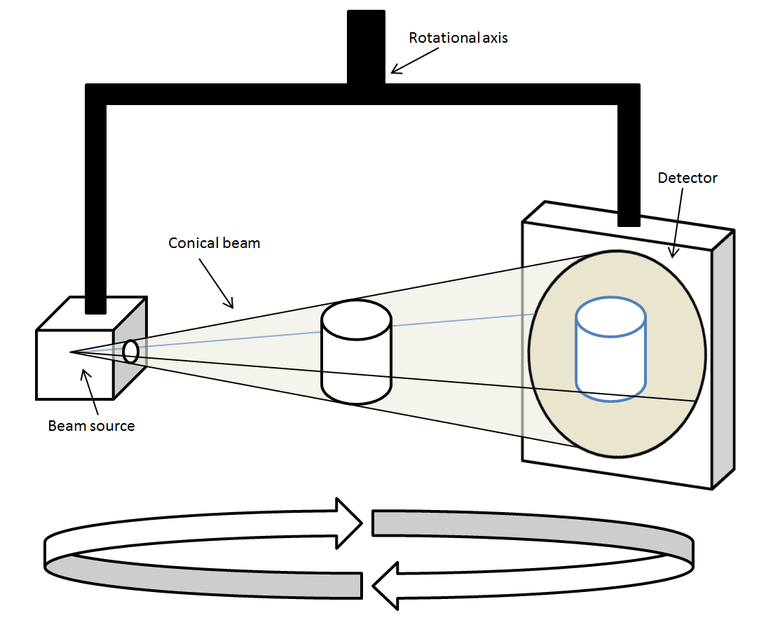
CT Scan: A difference between a conventional X-ray and a CT scan is that the X-ray tube and image receiver are fixed, whereas a CT scanner uses a motorized X-ray tube that circulates around the opening of a donut shaped ring, the gantry, which houses the radiation source.3 During a CT study, the patient will lie on a flat bed that slowly moves through the gantry while the X-ray tube rotates around the patient. The X-ray tube in the CT unit produces a narrow stream of fan-shaped X-rays directed at the body of the patient.3 Some of the X-ray photons are absorbed by the patient and some pass through the patient’s body and are received by digital detectors which are positioned directly opposite to the X-ray source. In a CBCT unit, the x-ray tube is fixed opposite the digital plate on a C-arm, which rotates as a unit around the patient.
Another key difference between MDCT and CBCT is the shape and size of the scanner itself. In its current form, a CBCT scanner looks like a small and condensed version of a MDCT scanner. Patient conveyance is not required with CBCT, though this does limit the area available to be imaged in a scan. The gantry and the FPD rotate simultaneously around the patient while shooting pulsed X-rays at the area of interest. The resulting X-rays strike the FPD on the opposite side of the source.1 The digital plate collects the 2D data set and the computer applies the FDK algorithm to the acquired data allowing for the reconstruction of a fully 3D image of the area of interest.
Data collected by these detectors is in the form of voxels. A voxel is a combination of both “volume” and “pixel,” which is a value on a regular grid in 3-dimensional space. The image made by the CT scanner consists of a square matrix of elements (the pixels) which also incorporates a depth measurement to become a voxel, or a volume element of the tissue of the patient.
Each time the X-ray source makes 1 full rotation, the CT’s computer will create these voxels using mathematical techniques and construct a 1-dimensional X-ray image slice of the patient.3 This process is then repeated to produce another image slice and continues until the desired number of slices is collected. These image slices are then either viewed singularly (2D) or stacked to form a 3D image of the patient that shows the skeleton, organs, and tissues as well as any abnormalities that the practitioner is trying to identify.3 Helical CT accomplishes this data collection in a single spiralized collection as opposed to aggregate single slices. (Figure 1)
Technology Advancement
X-ray imaging devices (traditional radiography, MDCT, CBCT, fluoroscopy, etc.) use a common X-ray tube configuration to produce the beam. An X-ray tube used in CT scanners produces X-rays, which are then projected in a fan-shaped beam due to collimators in the machine. In MDCT, these fan-shaped beams strike a 1D detector, which interprets the values received and sends them to the computer to be interpreted, by which an image is then formed. Conversely, as the name suggests, CBCT scans use a cone shaped beam in which the X-rays come from the common X-ray tube configuration, only this time they strike a 2D flat-panel detector (FPD).4 (Figure 2) These FPDs allow the CBCT to take multiple 2-dimensional X-ray images (basis projections) as opposed to the 1-dimensional X-ray images created by an MDCT scan.5 For the 2D data from the FPD to be utilized properly by the CBCT, it is able to use the same mathematical techniques and computer programs as a MDCT. However, these algorithms must be updated and transformed slightly to allow for the interpretation of the newly created 2D data. For the computer to properly portray the new type of data, the algorithm may be transformed using a Feldkamp-type reconstruction algorithm [FDK].2 The FDK algorithm is a mathematical transformation of the original algorithm used to construct MDCT images, only it now considers 2D data rather than 1D data and is what ultimately allows the CBCT to create its 3D image. This shift in data acquisition allows for reduced dose to the patient. The MDCT X-ray beam is lower in energy to allow for more differential absorption; in contrast, the CBCT study uses a high-energy X-ray beam which decreases the number of photons absorbed by the patient.
It should be noted that with increasing numbers of rows in MDCT detector arrays, the acquisition geometry approximates a cone beam system because the incident X-ray photons fall on a 2D area of detectors just as they do with FPD.4 (Figure 3)


CBCT – image quality and patient dose
When it comes to radiology and the ability of a chiropractor to diagnose a patient, A critically important factor is the quality of the image. Image quality is what allows the doctor to observe the study and make a diagnosis, whether that is looking for bone malalignment, broken bones, or foreign objects in the body. In many areas of healthcare today, diagnostic imaging is the gold standard in terms of diagnosis and assists in development of the treatment plan; this is precisely why the quality of the image makes all the difference in not only the doctor’s role, but also in the quality of care received by the patient.
Pictured below is a neutral lateral radiograph (Figure 4) and sagittal slice of a CBCT image of the same patient (Figure 5)
.png)
.png)
It is important to keep in mind that chiropractors take multiple images of the same anatomic region when using traditional radiographs to obtain the necessary detail needed for proper treatment. As we begin to consider patient dose, the effective patient dose to obtain an image similar to that of Figure 4 (lateral cervical radiograph) is 0.02 mSv (20 μSv) and for an AP cervical spine radiograph is 0.12 mSv.7
The description above quoted effective dose. Due to the individual sensitivities that different tissus have to radiation, it is important to be clear about the kind of dose being described: absorbed, equivalent, or effective.
Absorbed dose “is the energy deposited in a small volume of matter (tissue) by the radiation beam passing through the matter divided by the mass of the matter”.8 This is measured in Gray (Gy) and “is equal to a joule of energy deposited in a kilogram of substance.”9
Equivalent dose is a variation on absorbed dose that is focused on radiation-type based on its interaction with tissue. A change to units from Gray (Gy) to Seiverts (Sv) occurs after the absorbed dose is multiplied by a radiation weighting factor.8 This weighting factor is intended to allow for understanding of the amount of harm that is created by the various types of radiation (alpha, beta, gamma).9 In X-ray, the radiation weighting factor is 1.0, so in effect the absorbed dose of 1Gray (Gy) is equal to the equivalent dose in Seiverts (Sv).8
Effective dose multiplies the equivalent dose by a tissue weighting factor and is used to describe the effect of the radiation on the specific tissue that was exposed; effective dose is also described in Seiverts (Sv).
Understanding effective dose is necessary to evaluate the patient risk of having a diagnostic imaging study.
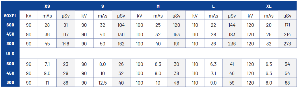
The effective dose obtained from Planmeca CBCT imaging supplies an effective dose range between 0.091 – 0.273 millisieverts (mSv) (91-273 microsieverts (μSv)) depending on patient size using standard settings at 30cm x 30 cm field of view, with effective dose reduced to .023-.068 mSv (23-68 μSv) with an ultra-low dose protocol. (Table 1) In contrast, the dose of a cervical spine x-ray examination has a total average effective dose of 0.2 mSv (200 μSv), and an MDCT has a total average effective dose of 3 mSv (3000 μSv) for the neck and 2 mSv (2000 μSv) for the head.10

As a result of this comparison between CBCT and X-ray imaging dose, CBCT supports doses being as low as reasonably achievable (ALARA) when considered against traditional X-ray examination, especially in cases in which extra views are recommended as in cases of trauma, radiculopathy, anatomic anomalies, and most chiropractic upper cervical techniques (UCTs).11
To understand health risks, it is helpful to understand what is allowed for people who work in occupations with regular radiation exposure. “The effective dose limits for a nuclear energy worker is set at 50 mSv in any one year and 100 mSv in five consecutive years. The dose limit for pregnant workers is 4 mSv from the time the pregnancy is declared to the end of the term.”9 For a frame of reference, the typical radiation an average individual in the USA can expect to encounter is 6.2 mSv (6200 μSv)12,13 or from background radiation alone is 3 mSv (3000 μSv) annually.10
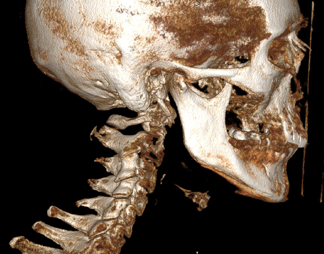
Figure 6 depicts a 3D surface rendered reconstruction.
.png)
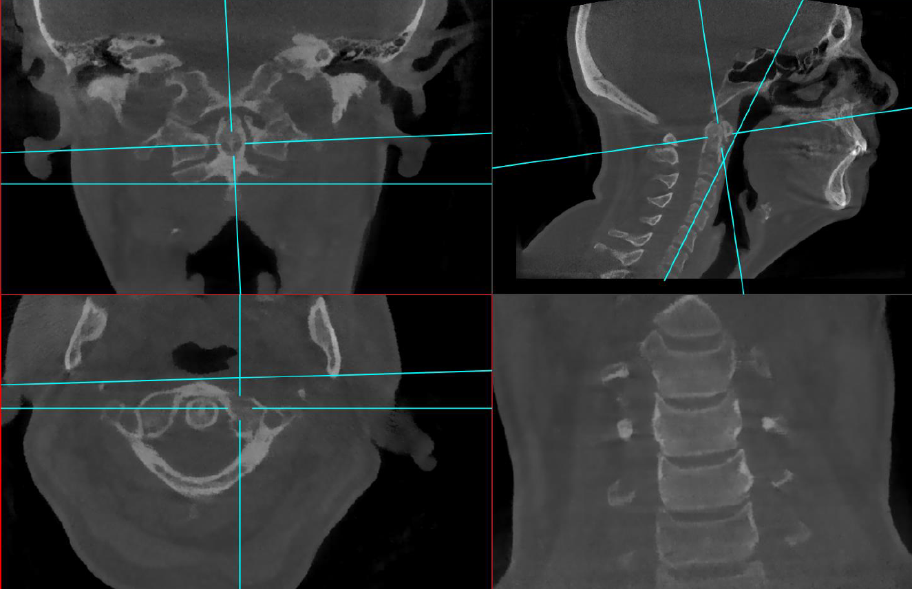
Figure 7 depicts a typical 3 view X-ray series; Figure 8 depicts multiplanar reconstruction (MPR) view using a single CBCT scan on the same patient.
.png)

Benefits of CBCT and 3D imaging
When considering chiropractic use of CBCT 3D imaging, there are several benefits available to the clinician, radiologist, and patient. These include less or equivalent radiation, better spatial resolution quality, wider variety of viewing angles, less time spent with image acquisition, easier patient positioning and improved patient experience, more precise treatment planning and protocol, reduction in electrical requirements, and reduced need for lead lined imaging suites.
In general, CBCT imaging last around 40 seconds and may be taken while the patient is either seated or standing; this provides both versatility and accessibility given that standing is not always a viable option for many patients.
Use of CBCT instead of traditional x-ray also negates the UCT specialty images that might be required in the thorough evaluation of the spine by chiropractors, especially those of the craniocervical junction and cervical spine. The ability to manipulate the image angles and perspectives replaces the need for multiple X-ray views to assess vertebrae and joints from different vantage points; this eliminates the need for retake imaging as well as multiple exposures to adequately assess an area.
Image resolution and the ability to create multiplanar reconstructions, combined with the lack of magnification and distortion in the image, provides for a diagnostic imaging study free of technical limitations inherent to traditional X-ray. With the use of CBCT we see a clear reduction in the time required for image acquisition while simultaneously improving image quality.
CBCT provides the ability to visualize and accurately discern complicated segmentation anomalies of the craniocervical spine and enhances the ability to identify pathogenic proximity to other anatomy as compared to X-ray. Assessing severity of joint disease and other disease that is not able to be well studied with radiographs, is also enhanced with CBCT applications [i.e. fusions not evident on traditional X-ray, calcium pyrophosphate deposition disease (CPPD)/pyrophosphate arthropathy involving the cruciate ligament complex and other paraodontoid structures, Schmorl’s nodes, and styloid process elongation (sometimes associated with Eagle’s Syndrome)]. The addition of CBCT in a chiropractic office not only improves the chiropractor’s ability to provide care to their patients but does so while supporting ALARA guidelines.
Future Applications
After reviewing both MDCT scans and CBCT scans, CBCT is an evolution in existing computed tomography technology rather than a new technology. In both cases, X-rays are still produced in similar fashion with the only real changes between the machines occurring with detection and the computer programming. This progress is like the development of new imaging sequences, receptor development, or enhancing magnet strength in MR.
Although the data requisition in CBCT technology is 2D rather than 1D in MDCT, multiple detector arrays on regular MDCT scanners approximates the data collection of the CBCT’s 2D surface. Essentially, this means that the special detectors used in MDCT are trying to recreate what the CBCT flat-panel detector already does during a scan. This mimicking of data acquisition is exactly what allows CBCT to essentially use the same algorithm that the MDCT scanner would use.
CBCT is seeing increase use in many different fields and is already used widely in dental imaging regarding the investigation of exact jaw pathologies such as tumours, inflammatory lesions, or for maxillofacial surgery.14 The 3D cone beam also aims to address the limitations present in 2D imaging on mammography with high contrast between pathological and normal breast tissue.15 CBCT is seeing advancements in both liver and lung imaging.16,17 CBCT machines are being developed to evaluate the entire spine; the technology is advancing quickly, and in the coming decades it may replace conventional radiography in evaluating for many diseases of the spine. High-quality CBCT studies will provide chiropractors with improved detail resulting in more accurate identification of pathology and therefore improved quality of care for the patient.
CBCT and MDCT are both forms of CT with CBCT having significantly reduced effective radiation dose. The reduced dose provided by CBCT will allow it in many cases to replace traditional X-ray examinations. There is clear evidence to support the fact that CBCT is not something new entirely but rather an evolution of an existing technology that may be beneficial for both patients and chiropractors alike.
Conclusion
Although CBCT has been used extensively in the dental industry for more than 2 decades, the ability for a single CBCT scan to replace a full cervical X-ray series is a recent development due to increases in capture device size. Technological advancement will likely soon allow all skeletal regions to be imaged by CBCT. MDCT and CBCT machines share similarities in X-ray generation and data processing, and as a result CBCT is an evolution of established CT and X-ray technology. With no increase in effective dose rates, and improvement in cross-sectional imaging capability, CBCT should be available as chiropractors seek to follow informed patient care with mind to ALARA principles and is best regarded as inside the scope of chiropractic practice in which radiation-based diagnostic imaging is currently allowed. It is our opinion that CBCT is a valuable and safe dose radiation-based diagnostic imaging study appropriate for access and use across the healthcare professions.
AUTHOR CONTRIBUTIONS
The need for this paper was conceptualized by JS and designed by JS and AK. The manuscript was drafted by AK and JS and edited with contributions by MR and KC. Radiographic and CBCT imaging provided by JS with patient consent. All authors read and approved the final manuscript.
CONFLICT OF INTEREST
The authors declare no conflict of interest with this article.
ACKNOWLEDGEMENTS
We would like to acknowledge Kira Scholten, who provided technical editing feedback. Thanks to SS who permitted image use (CBCT from Barcelona) and to Dr. Kerry Johnson who provided images for consideration.